POEtic project
The POEtic project is an european project whose goal is to develop a multi-cellular electronic circuit (a POEtic tissue or POEtic circuit) that implements the three axis of the POE model. This circuit will have the capacity to evolve by the mean of artificial evolution (P, or phylogenetic axis), to self-repair by using cellular redundancy and fault detection (O, or ontogenetic axis) and to learn by using artificial neural networks (E, or epigenetic axis).
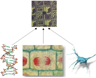
Figure 1: The three axis of the POE model merged in a single hardware chip
The key characteristics of the POEtic circuit are:
- Cellular structure. The circuit is composed of a 2D array of cells that are architecturally equivalent but can be functionally different. In this sense each cell is totipotent: it can implement any of the functionality present in the organism.
- Runtime reconfiguration. The circuit is capable of reconfiguring itself, for example to perform self-repair (detection of faulty cells and replacement of the faulty cell by a spare cell) or self-replication.
- Chromosome stored in each cell. Each cell of the POEtic circuit contains the whole description of the circuit, as in real biological organisms. This allows to build a whole organism from a single initial cell (growth process or ontogenesis).
- Scalable. New cells can be inserted at runtime. The neighbouring cells will transmit the genetic material to this newly inserted cell, which will in turn express a specific functionality.
- "Tissue" characteristics. All the cells of the POEtic circuit are connected to a sensor or an actuator. This makes the POEtic circuit akin to a biological tissue, hence the name POEtic tissue. This property makes the POEtic circuit interesting, due to its 2D array of cells, for applications like image processing, intelligent displays, tactile surfaces, etc.
- POE integration. The three axis of the POE model are implemented and possibly used together on the same hardware chip.
For more information on the POEtic circuit, please look at the official POEtic project site.
Evolution of the POEtic circuit
The LSA2 team members (Prof. Dario Floreano and PhD student Daniel Roggen) are working on the phylogenetic mechanisms (i.e. evolutionary algorithms) that will be used to evolve the POEtic circuit. This includes the definition of suitable genetic encodings and of appropriate genetic operators. The phylogenetic mechanisms developed here are motivated by two key problems, suggested by the literature on evolvable hardware, namely the scalability and evolvability problems:
-
Scalability: the genetic encoding is often a one-to-one mapping between the genotype and the phenotype. The result is that the size of the genotype grows with the size of the system to evolve (sometimes reaching thousands of bits in the case of evolvable hardware). A longer genotype generates a larger search space and evolutionary algorithms may fail to find solutions when the search space is too large.
-
Evolvability: the characteristics of the fitness landscape (e.g. ruggedness, epistasis, deceptiveness) have an influence on the performance of evolutionary algorithms. The fitness landscape is partly controlled by the genotype to phenotype mapping and by the genetic operators. To promote evolvability the application of the genetic operators should produce a fitness landscape that is suitable for evolution. This is often not the case with a traditional one-to-one mapping because genetic operators, mainly the crossover, generate rugged fitness landscapes which are more difficult for evolutionary algorithms to work on).
The system which has been developed is called morphogenetic system. It employs a genotype to phenotype mapping taking remotely inspiration from the gene expression mechanism that occurs in nature (where the functionality of the cells are encoded in genes that are expressed or inhibited by chemical signals of surrounding cells).
Hence, the genotype does not encode the functionality of each cell but rather conditions triggering the expression of specific functions.
The POEtic circuit contains a 32-bit RISC CPU which handles the evolutionary part of the system and also interfaces the organic subsystem with the external world. The POEtic CPU has been developed at the UPC in Barcelona/Spain. For more informations look at the POEtic project site.
Currently an assembler is available for this CPU. Programs can then be tested with:
- a simulation of the VHDL model of the CPU,
- or by downloading the program to the real CPU.
However, both approaches have drawbacks. The VHDL model offers a low level view of the CPU which is not suited to debug big programs. On the other side, the registers or the memory content can no longer be accesed when running a program on the real CPU.
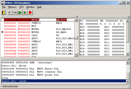
For easier development and test, a software emulator of the CPU has been written.
The user interface shows the memory content, program code, CPU status (e.g. registers, flags). The software also emulates ROM and RAM memories with a user-configurable memory map. Moreover, custom memory mapped peripherals can easily be added to the system by writing a DLL.
For more information check the POEtic CPU Emulator page.
A compact FPGA module has been developed, based on the APEX20K200E FPGA (200'000 gates) from Altera. Although it can be used standalone, its most interesting characteristic is that it is fully mechanically and electrically compatible with the Khepera miniature robot. This FPGA module provides a powerful reconfigurable hardware platform for evolvable hardware or evolutionary robotics experiments.
This board has been used to prototype systems related to the POEtic circuit. Notably a hardware implementation of a spiking network has been considered. For more information look at the FPGA module page.
Applications
Applications of the POEtic circuit to the control of the navigation of mobile robots (e.g. Khepera robot) using spiking neurons are under investigation.
Some preliminary results obtained with a software simulation of a PO circuit (software spiking network) have been published in Roggen, Floreano and Mattiussi 2003.
Hardware implementation of the spiking network on an FPGA has been considered in
Roggen, Hofmann, Thoma and Floreano 2003. Although the final implementation will be on the POEtic circuit, the FPGA implementation allowed us to define an architecture for the network and to estimate the space necessary for the implementation. The network connectivity was evolved to perform obstacle avoidance on a Khepera robot. Have a look at the following video, where the FPGA module, on top of the robot, can also be seen.
Publications